In Part 1 of our series on the Precision Alignment of Winders, we discussed the effects of misalignment on product quality and winder components. In Part 2 of this series, we begin the discussion on inspection and alignment techniques.
Winder Inspection and Alignment
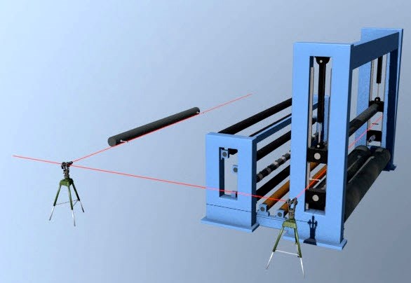
Image shows horizontal inspection using optical tooling
Alignment references
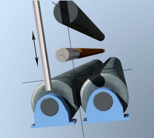
Most winder component alignment occurs in two directions: vertically and horizontally or “level” and “square”. Vertical inspections determine a component’s level condition. To complete horizontal inspections however, one must chose a reference line of sight or datum. It is general practice to create this datum line of sight parallel to the bottom of the rider roll fixed ways – this is the reference for all horizontal inspections.
Depending on a particular winder’s configuration, it is possible to use an alternate datum such as the rear drum. When doing so, the horizontal alignment then relates to the datum and the vertical alignment, or level, relates to earth.
Initial Survey/Inspection
The winder operates at high speeds. The web experiences short draws and there is a large amount of roll wrap. It is important to obtain a good picture of total winder alignment before making any adjustments. A thorough survey or inspection will obtain this information. Analysis of the data then reveals the best action for correcting the winder’s misalignment problems.
Unwind and Lead-in Rolls
Before completing the inspection of the unwind stand and its associated brake and clutch, one should load a new spool (or a spool that is known to be in good condition) into the unwind stand. If a new spool is not available, the following precautions are necessary:
- The spool should have no surface defects at the inspection points.
- Verify the spool diameters at the inspection points.
- Evaluate the spool’s journal and unwind saddle conditions.
- Repeat inspections after rotating the spool to check for run out.
The spool is then inspected to determine the vertical and horizontal alignment of the unwind stands. The stands should then be adjusted as necessary. Lastly, the clutch, brake, and unwind drive motor are then aligned to the spool.
Lead-in rolls are usually adjustable for their vertical attribute to compensate for parent roll non-uniformities. Sometimes operations improperly use this adjustment to compensate for gross misalignment between the unwind and slitter sections. This produces uneven stresses on the sheet.
It is recommended to inspect and align these lead-in rolls as needed. A scribeline or other match mark should be placed on the adjustment mechanism to show when the roll is level. This reference mark should be used as a starting point to compensate for varying parent roll characteristics.
In our next post in the winder alignment series, we will review the inspection process of the slitter section, rider roll ways, winder drums, rider roll and core chucks.