In Part One of our series on the importance of alignment in the reel section of your paper machine, we provided an overview of reel section alignment, some of the issues caused by misalignment, and the benefits of precision alignment. In this post, we provide more detailed information on how to align the various components that make up a reel section including the reel drum, reel rails, primary arms, secondary arms and spools.
As discussed in our previous post, proper reel alignment will ensure efficient sheet transfer, reel turn-up and a correctly wound sheet. By ensuring all reel components are properly aligned, your facility can benefit from improved production rates, increased machine speeds and higher profits.
Reel Drum
Ideally, the reel drum should be aligned level to earth and square to the machine centerline. A thorough alignment audit should also include the inspection of components leading into the reel section including lead-out dryers of the section preceding the reel, calender components, paper carrying rolls, and spreader rolls. This will determine if misalignment of the sheet exists prior to it making it onto the reel drum.
During the alignment audit, a visual inspection should be conducted to determine the overall condition of the reel drum stands. In most cases, these stands are not only reel drum supports/bearing mounts, but are also mounting supports for hydraulic cylinders, primary arm cross shaft assemblies, and the reel rails. Many times the reel drum is keyed to the stands. The stands are typically mounted to soleplates and dowel pinned in place. The reel stands should be routinely checked for tightness of hold-down and attachment bolts, cracked or broken frame pieces or mounting hardware, and worn bearings and/or bushings.
Consideration should also be given to the reel drum drive assembly, especially if the drum is found misaligned. Drive components should be aligned to tolerances of ±0.005”/inch in both the horizontal and vertical attributes.
Reel Rails
Dependent upon manufacturer design, reel rails should be set to design width (cross machine gauge dimension) and perpendicular to the reel drum with the cross machine gauge dimension being equal distance throughout the length of the rails. The drum-end of the rails should be parallel in the level attribute to the reel drum at or near the drum. Dependent upon the reel and rail design, alignment conditions may vary:
- Flat Rails – these rails will be set level throughout the length of the rails and should be level from one rail to the other, i.e. tending side rail vs. drive side rail.
- Sloped Rails – some rails are designed with a slope towards the reel drum, i.e. over the first ¼ of the rail length the rail will be set on a slope, with the low end at the reel drum. This slope uses gravity to hold tension of the reel set as it builds. Typically, the rails will level off so as the set builds to completion so it can be easily moved away from the reel drum by the secondary arms when the set is complete.
- Flat/Sloped Rails – these rails will be set level as mentioned above, but will then slope down, away from the reel drum. Typically these rails are flat throughout the length of rail where the reel set is made, then slope downward, away from the drum so as to use gravity to move the reel set on down the rails, away from the reel.
Whenever possible, manufacturer print specifications should be referred to for aligning reel rails.
Primary Arms 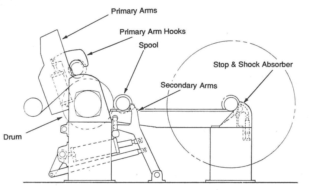
Dependent upon manufacturer, the reel primary arms will be operated by mechanical means (hydraulic or motor driven cross shaft & gear assembly). Both generally have a means of adjustment. The reel primary arms should be aligned such that the spool will remain parallel to the reel drum throughout its downward cycle. This should be checked in two positions: the empty spool’s initial point of contact with the drum (the turn-up position) and when the spool is lowered to just above the rails. In the turn-up position, the arms should be inspected for parallelism to the drum in the horizontal and vertical attributes. When the spool is lowered to just above the rails, the spool needs to be inspected for parallelism to the drum in the vertical attribute only. If the primary arms are found misaligned, corrections should be made to the timing of the arms such that the spool is parallel to the drum within ±0.005 across the width of the spool face.
Primary arms that are operated by motor driven cross shaft and gear assembly are prone to paper dust build-up in the gear teeth and excessive wear on the gear teeth. When performing the initial inspection, these gears should be inspected visually and mechanically. Visual inspections will show wear of components, dust collection and if there are any broken parts. Mechanical inspections are made by checking the root clearance of the gears and backlash on the gears. Many times, primary arms can be aligned to a better condition by closing up the root clearance and setting the backlash the same on tending and drive side gears. Some cross shafts will consist of two separate shafts with a coupling. The coupling allows for each end of the cross shaft to be adjusted for gear clearance and rotated independently for setting the timing of the primary arms.
Secondary Arms
Secondary arms are typically used for two purposes:
- To apply pressure on the spool as the reel set builds. This applies tension to the spool against the drum for a properly wound reel set.
- To remove the reel set after completion. The arms move the reeled spool away from the reel drum and down the rails for storage until it is moved to the winder.
Secondary arm pivot pins should be aligned to print specifications for their location in the overall footprint of the reel section. These pivot pins should be aligned level and square to ±0.005”.
Typically secondary arms do not require routine inspection/alignment. However, if pins become worn, parts become damaged, or the secondary arms are not operating properly; the alignment of the pivots should be checked to eliminate misalignment as a potential problem.
Spools
Spools should be monitored by mill personnel because they become worn and damaged over time and lead to potential problems in reel operations. Spool covers can become worn and wear can vary, causing spools to be larger on one end than the other or larger in the middle than ends or vice versa. Spool bearings will wear and journals can be bent. When performing alignment inspections of the reel primary arms, the best reel spool should be used to allow for the most accurate alignment data.
For more information on how the precision alignment of paper machine components can help to improve production at your mill, please contact the OASIS Service Center nearest you.
Learn more about the causes of machine misalignment.