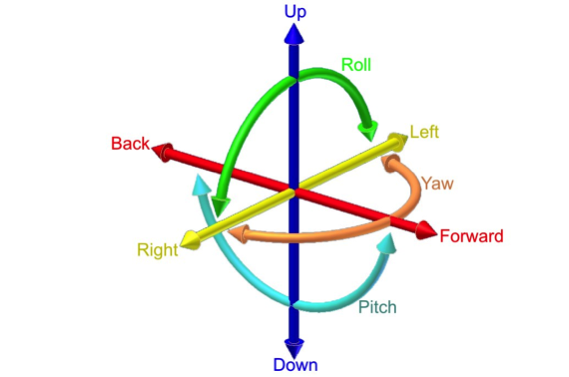

The six degrees of freedom: forward/back, up/down, left/right, pitch, yaw, roll (via Wikipedia)
The many uses of the word “alignment” describe a structure between objects, ideas, or people. When mechanics use the word alignment, they generally mean the relationship between one mechanical component and another. In a three dimensional world, that implies that the component relationship is described in a way that leaves no degrees of freedom unaccounted for.
Although there may be other degrees of freedom affecting a body (such as thermal growth, compressibility, and nuclear decay) they can usually be neglected. The question is, “How do you describe the relationship between the geometric bodies?”
The invention of Cartesian coordinates in the 17th century by René Descartes (Latinized name: Cartesius) revolutionized mathematics by providing the first systematic link between Euclidean geometry and algebra. Using the Cartesian coordinate system, geometric shapes (such as curves) can be described by Cartesian equations. Cartesian coordinates are the foundation of analytic geometry, and provide enlightening geometric interpretations for many other branches of mathematics, such as linear algebra, complex analysis, differential geometry, multivariate calculus, group theory, and more. Cartesian coordinates are also essential tools for most applied disciplines that deal with geometry, including astronomy, physics, engineering, and many more.
With a way to calculate the relationship between bodies in finite directions of translation and rotation, we can now describe that relationship in standard form. A body who’s centroid is described as (x, y, z), (i, j, k) in relation to a known datum or another body that is at (a, b, c), (u, v, w), can be located in relative space using simple geometry and mathematics.

Centroid of a blob (via Wikimedia Commons)
So how do we use this knowledge in a practical way, in everyday life, as a maintenance or project engineer? A body’s centroid is not a very practical thing to use as a measurement point. Determining its orientation in space is impossible. And what is the datum or the other body?
The key is to choose components of the body that can be measured practically and can also be described as a single point, or a relation of single points. This concept is called point reducibility. Point reducibility is the point resulting from a more complex measurement. For example, measuring a circle yields a center point; measuring a cylinder yields two end points; or measuring three intersecting planes yields a corner point. If the body can be described by a vector (or the relationship of two distinct points that form a vector) relative to another body or datum described in the same way, then the problem with describing alignment is solved.
What’s more, if a series of bodies is described by similar vectors relative to the same common reference body’s vector or datum, then the alignment of those bodies can be described as well. In other words, if we can do away with all the complex vectorial mathematics and relate the position of a body by comparing two points, it makes interpreting alignment a lot simpler. Furthermore, if we make one of those points zero, then the comprehension of the alignment is that much easier.
Alignment of several rolls in a machine described only by the front side center points relative to the back side
Practically speaking, there are two types of alignment we need to be concerned with when dealing with bodies in relative space. The bodies need to be located relative to each other and at a specified angle to each other. We can expand this generalization into two common categories of alignment; parallelism and perpendicularity. In either case the component being aligned can be described using a point’s coordinates and the relative position of a second point.
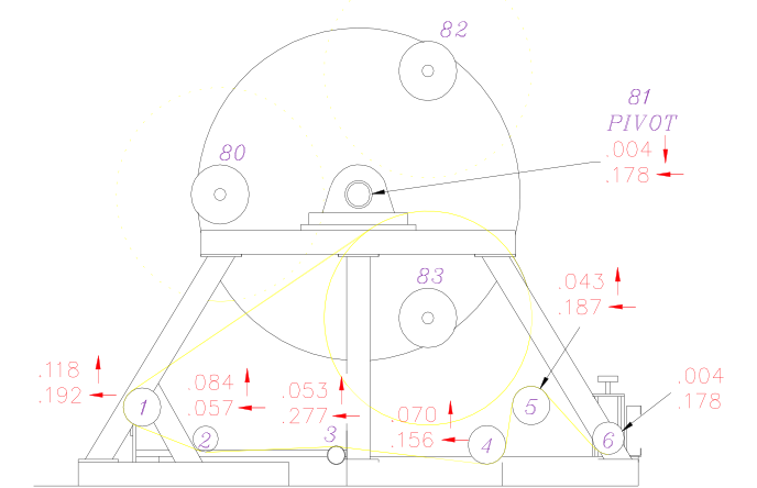
The way we actually measure the points on these individual bodies is by measuring point reducible features. In the image below for example, cylinders are reduced to two end points. We could measure one end of a side frame piece at a specific location relative to the other end to report its alignment in the horizontal attribute (square) or the top of a frame piece to find the vertical alignment (or level). Another example would be to mathematically extract the ends from a cylinder shape constructed from a series of measurements using a portable coordinate measuring machine such as laser tracker.
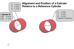 The same cylinder could also be measured and located using specific horizontal and vertical tangential offset measurements using an optical transit or theodolite and precision scales. In either case, the two specific points can then be compared to each other to determine their alignment in the Cartesian coordinates of choice as shown in the image to the right. With the proper instruments, some knowledge of the parts, machines, or bodies being measured – and some creativity – almost anything can be aligned.