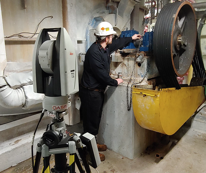
Laser trackers continue to be the most buzzed about innovation in the field of precision measurement. With all the talk about this advanced technology, new terminologies may be discussed that are unfamiliar to some. In this post we provide you with definitions for terms you may hear during a precision measurement or machine alignment project where a laser tracker is being used to gather dimensional measurement data.
| Laser Tracker Terminology | ||
|---|---|---|
| Laser Tracker | 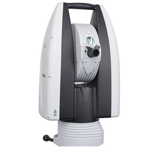 | A highly accurate portable coordinate measuring machine that uses angles and laser distance. Metrology software uses the output data of the laser track to determine form and position relative to a datum. |
| T-Probe | 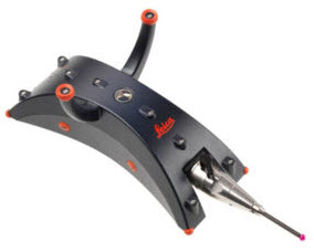 | A handheld probe that combines 3D capabilities with advanced photogrammetry techniques to extend the measurement reach of the laser tracker with a variety of styli and extensions. |
| SMR (Spherically Mounted Retroreflector) | 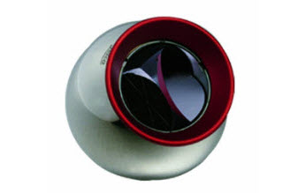 | The SMR (Spherically Mounted Retroreflector) consists of three first surface mirrors mounted at 90º to each other forming a corner. Any light ray entering the SMR is reflected exactly back (180º) to the laser tracker. |
| Nests | 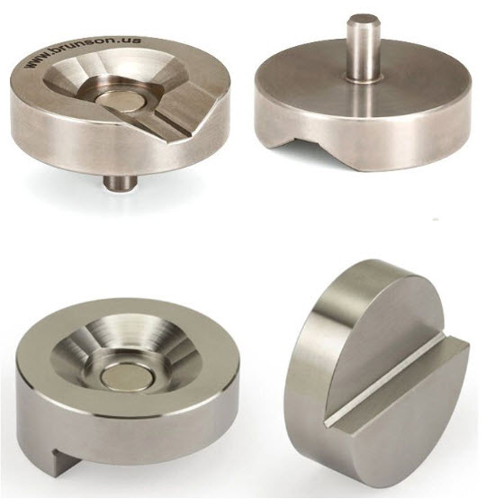 | Precision machined magnetic tooling for an SMR used to locate a laser tracker in relation to the machine or component being measured. Pin nests (shown on the top) can be used to measure holes. Edge nests (shown on the bottom) are used to locate the edge of a frame or component. |
| Drift Nests | 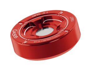 | Sometimes called "pucks”, drift nests provide a temporary magnetic holder in almost any location or surface. Using a drift nest allows for tying the measurement data together in a common reference frame. Drift nest are also used to verify that an instrument has not drifted during a measurement session. |
| Coordinate System | 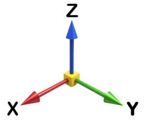 | The coordinate system (reference frame) is set to reflect the X, Y, and Z coordinates of all measured points relative to an origin point and indexed relative to other points or components of the machine or piece being measured. In most cases, the X axis is indexed parallel to the machine or component centerline and the Z axis is indexed relative to gravity; that is perpendicular to the tangent plane on the earth’s surface. |
| Component Alignment Callouts (dX, dY, dZ) | 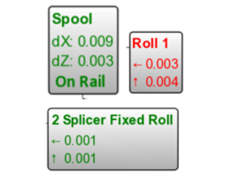 | These terms reflect the difference or change in distance, between measured points for the corresponding coordinate. Image shows a distance of 0.009” for the X-axis and 0.003” for the Z-axis. OASIS also represents component alignment directions with arrows as defined by the legend icon in the drawing. |
| Six Degrees of Freedom (6DoF) | 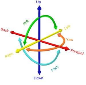 | Six degrees of freedom (6DoF) refers to the freedom of movement of a rigid body in three-dimensional space. Specifically, the body is free to change position as forward/backward (surge), up/down (heave), left/right (sway) translation in three perpendicular axes, combined with changes in orientation through rotation about three perpendicular axes, often termed yaw (normal axis), pitch (transverse axis), and roll (longitudinal axis). |
| Point Cloud | 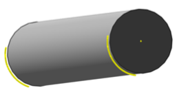 | Data is gathered by scanning the surface of a component at pre-determined distances. The data can then be used to generate circles, spheres,cylinders and other geometric shapes or to develop polygonized mesh or other surface. The point cloud can also be exported in several useful formats including IGES, STEP, and other popular formats used by 3D modeling software. |
| Contour and Whisker Plots | 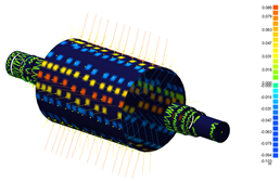 | Points are recorded on a surface and then compared to a known or measured shape such as a cylinder, sphere, surface, plane, line, etc. The distance and direction of the point from the shape is represented by a shaded color plot and/or vector of an equivalent length. In those cases where the vector may not be large enough (in relation to the shape), it can be scaled to give a visual representation of the data points. It is also colorized to indicate compliance or non-compliance with a tolerance. |
| References | ||
|---|---|---|
| Baseline | 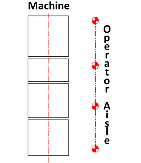 | A reference line parallel to the machine centerline. It is typically represented by Stainless Steel Target Bushings (SSTBs) or brass plugs embedded in the floor on the operator side of the machine. In the case of newer, freestanding equipment, this reference is installed in the cross-machine direction directly in the frame or soleplates. |
| Brass Plug |  | A monument embedded in the floor with an affixed prick punch mark used as a reference point on a baseline. |
| Stainless Steel Target Bushing (SSTB) | 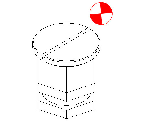 | A machined bushing designed and used exclusively by OASIS in the installation of baselines. It performs the same function as a brass plug but is far more accurate as it can accept an optical target or a nest for an SMR (Spherically Mounted Retroreflector). |
| Procedures | ||
|---|---|---|
| Buck-In | Setting a laser tracker reference system or computer model to at least two reference points such as Stainless Steel Target Bushings (SSTBs), brass plugs (BPs) or to the axis, plane, or reference points of a machine component. | |
| Planizing | Setting a laser tracker reference system or computer model parallel to a given plane. This plane can be defined by a minimum of three points. This allows profiling and measuring components parallel to that plane. | |
| Alignments | When referring to part inspections, the term alignment commonly refers to the alignment of data points to a CAD model of the part. There are many types of alignments in the 3D metrology industry. OASIS commonly uses point-to-point, best-fit alignments when moving a measuring device such as a laser tracker, from one location to another during a machine alignment job. | |
Interested in learning more? Check out Why Laser Trackers for 3D Precision Measurement? In this article we provide an overview of of how laser trackers work and describe just a few of the industry applications where laser trackers excel.
If you would like a demonstration of our laser tracker capabilities at your facility, please contact us to schedule. For additional articles on laser trackers and other precision measurement instruments, be sure to visit our Resources page.