Accurate alignment is essential to the performance and longevity of hydropower equipment. As turbine assemblies age, achieving proper alignment during rebuilds or upgrades depends on understanding each component’s true geometry. Presented at the Innovation Powerhouse during Clean Currents 2025, this article explores how advanced 3D scanning and reverse engineering support precision alignment and machine measurement—helping hydro facilities maintain efficiency and reliability across every maintenance cycle.
Using precision measurement and digital modeling to restore hydro equipment to OEM-level accuracy.
Legacy hydro equipment demands precise alignment and accurate dimensional data before any restoration work begins. At OASIS, our field alignment specialists support hydro operators with measurement strategies that eliminate guesswork and keep outages on schedule. The following article outlines how advanced 3D scanning and reverse engineering methods help teams recover critical geometry, validate interfaces, and prepare components for machining or rebuild work.
Aging Infrastructure and Limited Documentation
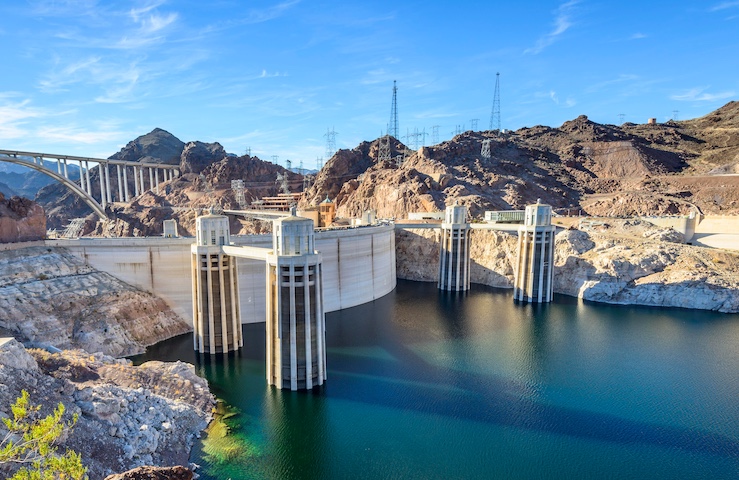
Many hydroelectric plants in operation today were constructed decades ago. Over time, mechanical wear, corrosion, and repeated refurbishment cycles alter the original geometry of turbine runners, propellers, and other critical components.
In many cases, the original engineering drawings or OEM reference data are no longer available. As a result, teams responsible for replacement or repair often rely on manual measurement methods or outdated prints. This introduces dimensional uncertainty, increases the risk of misalignment, and can lead to extended outage durations when replacement parts fail to meet fit or tolerance requirements.
A reliable dimensional baseline is essential before any component repair, reverse engineering, or fabrication is initiated.
3D Scanning as a Dimensional Baseline Tool
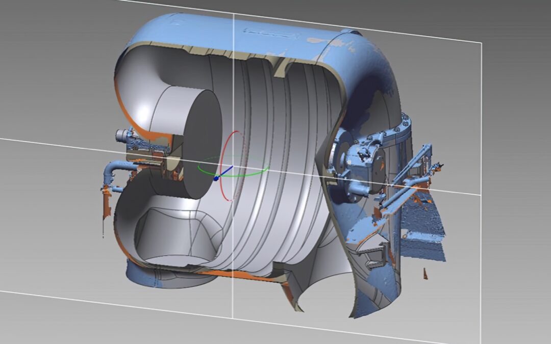
Modern 3D scanning technology provides a non-contact, highly accurate method of capturing a component’s as-found condition. Using laser trackers, structured-light scanners, or portable coordinate measuring machines (CMMs), millions of data points can be collected to produce a high-resolution point cloud representing the true geometry of the part.
This data is processed using reverse engineering software to generate:
- As-found surface models documenting existing wear or deformation
- As-designed geometry reconstructed to reflect OEM intent
- Parametric CAD models for machining or finite element analysis
This process allows engineers to quantify deviations from the nominal geometry and make informed decisions before manufacturing begins.
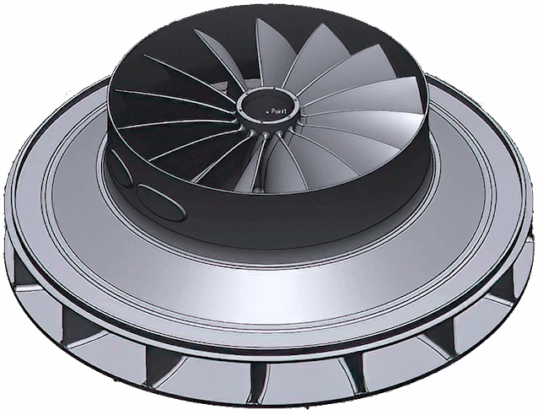
Application Example: Turbine Runner and Propeller Refurbishment
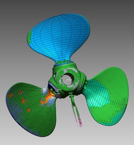
During refurbishment of a hydraulic turbine runner and propeller assembly, 3D scanning was used to capture the complete surface geometry of each blade, hub, and shaft interface.
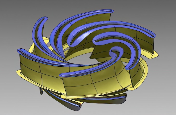
The resulting models provided a dimensional reference for:
- Re-creating missing engineering drawings
- Designing replacement components such as the center hub
- Conducting a virtual fit-up between scanned and newly modeled parts
By validating the assembly in a digital environment, all alignment and interface tolerances were verified prior to machining or installation. This reduced the risk of rework and minimized field adjustments once components were returned to service.
Reverse Engineering for Functional Restoration
Reverse engineering extends beyond shape reproduction. When combined with geometric dimensioning and tolerance (GD&T) analysis, it allows engineers to:
- Identify deformation due to stress or erosion
- Detect asymmetries that may affect balance or hydraulic performance
- Apply corrective geometry to improve flow or efficiency
The digital models created through this process become the foundation for manufacturing replacement parts or performing structural and fluid-dynamic analyses. In hydro applications, this can mean restoring turbine performance to original specifications or optimizing for improved efficiency and load balance.
Integration with Machining and Inspection
Dimensional data obtained from 3D scanning can be transferred directly to CNC machining platforms, ensuring consistent reference between the digital model and the physical part.
Following fabrication, final verification scans or laser tracker inspections confirm dimensional compliance within the specified tolerance range.
This closed-loop workflow — scan, model, machine, verify — provides traceability and repeatability throughout the process, reducing the potential for cumulative error between design and execution.
Long-Term Data and Lifecycle Tracking
Beyond a single project, archived 3D data creates a foundation for future maintenance and asset management.
A complete digital model of a runner or impeller allows engineers to:
- Monitor dimensional wear over multiple maintenance cycles
- Compare future scans against baseline data for degradation analysis
- Plan replacement intervals based on measurable change rather than estimated runtime
This approach supports data-driven decision-making and improves the predictability of maintenance schedules across a fleet of hydro units.
Key Takeaways
3D scanning and reverse engineering have become standard tools in the modernization and maintenance of hydroelectric assets.
By establishing a precise digital baseline and validating geometry before fabrication, engineers can eliminate dimensional uncertainty, reduce outage duration, and ensure long-term component reliability.
These technologies bridge the gap between legacy equipment and modern manufacturing methods, supporting the continued operation of hydro facilities for decades to come.
OASIS Alignment Services provides on-site machine alignment and precision measurement solutions across North America. As part of the Measurement & Alignment Services Division of In-Place Machining Company, OASIS supports industries where accuracy, reliability, and uptime are critical to performance.
For more information on our services or to schedule a site visit, contact us today.