What is level? Level is an imaginary plane level to Earth at any particular tangential point on our planet. Due to Earth’s gravity (which is approximately normal to the curvature of the Earth) the level plane can be measured quite easily by several methods.
A very crude but effective way to measure level is by using columns of water. Communicating vessels will come to static equilibrium, hence forcing the columns of water to the same level. A simple vial level (sometimes referred to as a tubular spirit level) can only measure gravity in one direction. Vials can be combined to measure more than one direction at a time. A circular bull’s eye level can achieve measurement of the level plane unilaterally. All of the latter require the intervention of the human eye to interpret the level condition.
More sophisticated ways of measuring the level plane are pendulums, digital inclinometers, accelerometers, and optical levels. The optical level is commonly used in industry to measure elevations between points by using Earth’s level as a reference (or constant). By calibrating the level vial to the optical line of sight, targets can be sighted and measured compared to the level plane. But why do we need to measure level? In most cases, we actually don’t need Earth’s level as a reference for the process itself, but we do need it as a reference for the measurement devices. Optical instruments rely on the level plane to ensure continuity between devices and between device positions. It is a constant and universal reference that can be used by most types of optical instruments and laser trackers.
The Common Reference
 Level is a universal reference that is consistent everywhere on the machine. The problem has always been trying to establish a reference for the other attributes of the alignment equation. It is quite simple and sometimes a lot quicker to base the alignment of one component on another. When the parallelism of those two components is essential, then the relative alignment method is adequate. However, when the alignment of an entire machine is considered, basing the alignment of an entire line on adjacent components can lead to substantial accumulation of error. Even basing the alignment of components to one component is risky if that datum component is not truly representative of the machine’s average alignment.
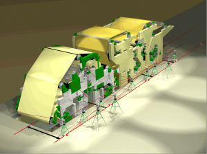
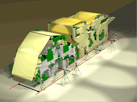
A much better approach to parallelism alignment is to base every measurement on a common reference. A common reference is a reference that can be used anywhere on the machine. Using optical instruments, a typical reference for parallelism alignment is an offset baseline. Using a laser tracker, a common reference is comprised of an array of reference targets all measured from a unique location. Determining the best offset baseline is the result of a statistical analysis of the individual centerlines of the components of the machine. The trend line found as a result of a centerline survey determines the best-fit centerline and hence the offset baseline. Of course, if a machine is properly erected from scratch using a centerline and a parallel offset baseline, the need to find the best-fit centerline is not required.
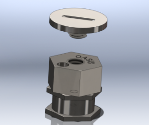
Unfortunately, target locations, comprised of brass or steel monuments, are often left unprotected and therefore subject to damage or destruction. The best baseline monuments are made of stainless steel and include a target locator and protective cover. Optical filer targets or laser tracker tooling is inserted in the locator whenever the reference target must be read.
The know-how and expertise required to properly assess a machine’s centerline is crucial to proper alignment. Independent of the metrology tooling used, the basic principles required to properly align machines are the same.


