When asked recently why the precision alignment of drive components is important to their paper mill, our customer responded with:
“Proper shaft alignment is a critical component of realizing reliable and efficient operation of rotating equipment. At a facility such as ours that operates 24/7 and has high speed equipment, a misaligned machine component can fail quickly and result in many hours of unplanned downtime. By taking the time to properly align our rotating equipment to a precision state, we are seeing significant reductions in unplanned downtime, contractors’ cost, and parts cost. It pays to do it right the first time!”
Alignment is critical to all types of drives, whether they be driven by belts, chains, gears, or shafts. Performing precision alignment of drive equipment helps eliminate catastrophic failures which can create unscheduled downtime, loss of valuable production time, extra in-house or contractor man-hours, and component costs. Proper shaft alignment ensures efficient transmission of power to the driven equipment and can extend the life of the rotating machinery as well as the components that make up the drive configuration.
Causes and Symptoms of Drive Train Misalignment
There are several causes of machine misalignment including:
- Improper equipment alignment upon installation
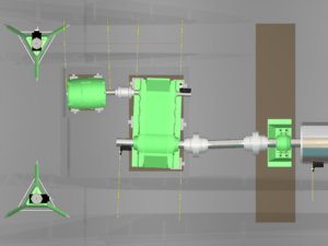
Image shows misalignment of motor and gearbox – this will lead to excessive stress on the shaft, bearings and couplings.
- Time and wear
- Building movement or settlement
- Component changes occur without consideration for precision alignment – motors, gearboxes, rolls
- Thermal growth not accounted for
If your line is experiencing excessive vibration and noise, overheated bearings, and premature bearing and/or coupling and seal failures, the chances are good that there is misalignment in one or more of your drive components.
Key Steps in Avoiding Drive Train Issues
- Do it right the 1st time!
- When replacing a drive component(s), utilize the precision alignment method that best suits your situation, whether it be optical alignment tooling, a laser shaft alignment system (LSAS) or 3D metrology instruments such as laser trackers. If shaft offsets or shaft angular misalignment are too excessive, this can result in overheated bearings and premature bearing failure.
- Ensure the correct jackshaft length is used – incorrect jackshaft lengths often lead to coupling failures.
- Know your bearing types – Some situations require held bearings and floating bearings, so if the float is not set in the proper direction, this can result in an overload of a bearing, producing excessive temperatures which then can lead to bearing failures.
- Have a Preventive Maintenance Program that includes regularly scheduled drive checks for vibration, bearing and coupling temperatures, and drive alignment verification.
Effective Planning for Drive Train Alignment
When developing an alignment plan of your driven equipment, it’s critical to know the current alignment condition that exists, the drive type, and the required alignment tolerances. Because there are many different drive configurations, each will require their own alignment approach.
- Lineshafts – many older paper machines are driven by a lineshaft which require alignment of the shaft itself, as well as taking into consideration the configuration of the gearboxes and all of the driven components.
- AC/DC Drives – most other paper/converting lines are driven by AC or DC drives. These drives are coupled to the high-speed side of a gearbox which requires achieving tighter alignment tolerances.
- Roll to Drive Alignment – depending on the alignment situation that you are faced with, the alignment approach may vary based on moving the roll or moving the drive components.
- Closed Gear Drive Train– in the case of a closed gear machine, the input shaft is the fixed component and cannot be moved. Therefore, it must be the reference for the drive alignment.
- Open Gear Drive Train – an open gear drive train allows for more flexibility in that you can adjust the pinion to best fit the alignment condition back to the gearbox.
It is important to note that there are many factors that can prevent you from achieving acceptable drive alignment tolerances. For example, insufficient bolt hole clearances within the drive components, or an insufficient amount of shim to be removed when the inspection data calls for that. In a future post we will discuss these situations and the solutions for correcting them.
Looking for more information? Check out these related articles:
Measurement Tool Spotlight: Laser Shaft Alignment Systems
How to Align Machines – Shaft Alignment
Please contact us if you would like to discuss the ways that OASIS can assist with increasing efficiency at your location. Be sure to subscribe to our resources for regular updates on precision measurement and machine alignment tools, methodologies, case studies and more.Lo, you may find value in these related articles: